What full cutoff actually means: 90°, 80° and 70°
ULOR 0%, uplight U0, IES full cutoff, G*1 to G*6: the angles behind 'no light above the horizon', why the law stops at 90°, and why good design does not.

 Explainer · Standards
In diesem Artikel
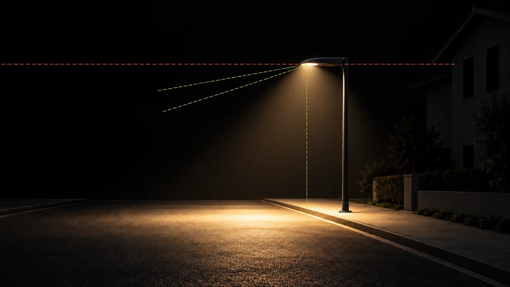
"The luminaire must not emit above 180° downward." You hear it in tenders, in council meetings and in product sheets, and it means one thing: the whole lower hemisphere, nothing above the horizontal plane, which is 90° measured from the nadir (straight down). That single line is what most light pollution laws actually require. It has several names.
- EN 13201-2 G*4 allows
- 100 cd/klm
- EN 13201-2 G*6 allows
- 100 cd/klm
- IES full cutoff
- ≤ 10 % of lumens at or above 80°
- The law (ULOR 0 % countries)
- Allowed; limited by G* class and by window illuminance limits
The horizon: 90° from nadir
- ULOR 0% (upward light output ratio): no share of the luminous flux above the horizontal. Croatia, Slovenia and Lombardy write it into law this way.
- Uplight U0: the U in the IES BUG rating (backlight, uplight, glare). U0 is the only value a dark-sky specification accepts.
- *G6* in EN 13201-2: zero intensity at 90° and above. G4 and G*5 still allow 10 cd/klm at 90° and only reach zero above 95°.
- IES full cutoff: zero candela at or above 90°, and no more than 10% of the light at or above 80°. Semi-cutoff allows 5% and 20%.
80° and 70°: where glare and trespass live
Light just below the horizon does not reach the sky directly, but it is the light that blinds drivers and enters bedroom windows. That is why EN 13201-2 (Annex A, table A.1) limits intensity in the 70° to 90° band. Per 1,000 lumens of luminaire output: *G4 allows 500 cd at 70°, 100 at 80°, 10 at 90°; G5 allows 350, 100 and 10; G6** allows 350, 100 and 0. A narrower cone, "160°" (nothing above 80°) or "150°" (nothing above 75°), is not required by any law we know of. It is a design choice, and it is where the real difference between a catalogue luminaire and a calculated one shows up.
| Class | ≥ 70° | ≥ 80° | ≥ 90° | Other |
|---|---|---|---|---|
| G*1 | no limit | 200 | 50 | none |
| G*2 | no limit | 150 | 30 | none |
| G*3 | no limit | 100 | 20 | none |
| G*4 | 500 | 100 | 10 | zero above 95° |
| G*5 | 350 | 100 | 10 | zero above 95° |
| G*6 | 350 | 100 | 0 | zero above 90° |
Why the law stops at 90° and design should not
A catalogue offers a handful of distributions. To meet the road class at its weakest point with a fixed curve, the designer turns the flux up, and the surplus spills into the 70° to 90° band, onto facades and into windows. Calculating the distribution from the street reverses that: the curve is shaped to put the required luminance on the road and the pavement, so the intensity near the horizon is whatever the road needs, and nothing more. On a residential street in Pula that was 45.8% less luminous flux for the same M4, P3 and P1 classes, with 0% uplight by construction.
“Light where it is needed. Darkness where it belongs.”
What the road lighting norm covers, and the three things it leaves out: colour temperature, upward light and an upper limit.
Design the distribution a street needs, then choose the luminaire that delivers it.

Lighting designer with more than 35 years in architectural and urban lighting and over 50 international awards. Founder of Taman.